I Description
Tridimensional wrapped CRGO core transformer is a new high performance transformer with more reasonable structure, better performance, less production cost.
The tridimensional wrapped CRGO core like a new innovation, comparing to conventional tranformers, it changes magnetics structure, drastically depresses no-load loss, no-load current and noise level. And thus reduce transformer’s running cost.
II Structure of tridimensional wrapped core
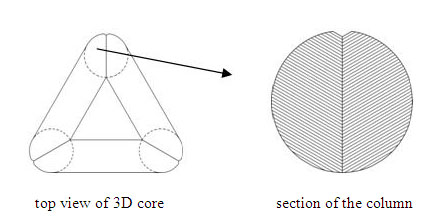
2.1 This tri-dimensional wrapped core is comprised of three cores which are exactly same!

| top view of 3D core |
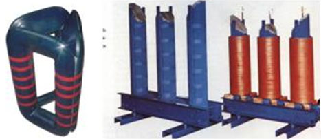
Real photo of single core |
Section of single core |
2.2 Section of the three columns is round and lamination factor reaches 99%

III Technology specialties
3.1 Wrapped core, no joints
Each single core of this tridimensional wrapped core is wrapped from very long CRGO strips and so magnetic circuits distribute even in each position, avoiding to form high resistance area because of laminating joints, and avoiding magnetic flux density distort at joining positions.
3.2 After wrapped, core is annealed
During slitting and wrapping, because of stretching and magnetic allision, performance of CRGO is effected too much. After annealed in vacuum annealing furnace, magnetic performance is recovered. Also high temperature annealing can eliminate the innerstree occurred during wrapping.
3.3 Tridimensional wrapped core doesn’t need clamping tools
Stacking factor of the wrapped core itself reaches 98% and the tridimensional core only need to be bounded by insulation tape during assembly, no need steel clamping tools which may worsen core performance.

3.4 High mechanical automation, few human factors
The whole production progress of tridimensional wrapped core, from CRGO strip slitting, diagonal slitting to wrapping and annealing, is finished by machines automatically, very few human factors.
IV Characteristics of the tridimensional cores
4.1 Optimized magnetic circuit structure
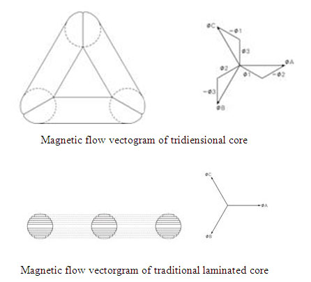
Magnetic circuits of each phase are completely symmetrical; circuit length is completely same and the sum of total length is the shortest (comparing to any other core structure); No-load current of each phase is completely balanced, and the third harmonic will not be occurred.

4.2 Drepressing no-load loss, no-load current and noise level drastically
There are no joints between interlamination; Magnetic flow direction is completely same to grain orientation of CRGO; And the core will be annealed.
4.3 Unique natural ventilation and radiation
The three yoke blocks are in 60 degree to each other. After adding coils, a natural “drawn chimney” is formed. Temperature difference between yoke upper and lower sections is about 30-40℃ and there will be air convection inside the “drawn chimney” which will radiate the heat very quickly. Thus it depresses the temperature raising of transformer and raises over-load capacity of transformer.
4.4 Compact structure, saving material and space
Section of the core column is round, min. diameter and so the three phase windings are more compact, saving copper materials and reducing transformer sizes.
4.5 Theft deterrent: 3D wound core is a whole body, can’t be dismantled and coils can’t be removed. And whole weight of one 200kVA transformer is 650kg.
V Comparation between tridimensional core and conventional laminated core (under same CRGO material, same column section area, same window height, same central distance between columns)
5.1 CRGO material saved
1) Weight of 3D core is about 10-15% lighter than laminated core
2) Material waste during processing: 3D core than that of laminated core
5.2 Copper coil material is saved about 2~3% less than that of laminated core
5.3 No-load loss and no-load current are less
1) No-load loss is 30% less
2) No-load current is 70% less
5.4 Noise level is reduced about 7~10 dB.
5.5 Three-phase balance: 3D core is three-phase balanced completely. For laminated core, magnetic circuit length of two side columns is 20% more than that of the middle column.
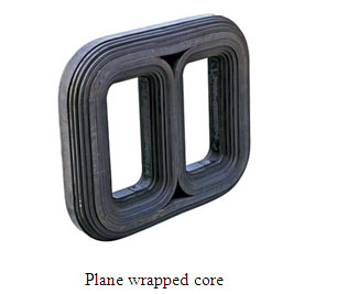
VI Comparation between tridimensional wrapped core and plane wrapped core (under same CRGO material, same column section area, same window height, same central distance between columns)

6.1 CRGO material is saved: weight is 15% less
6.2 No-load loss is about 10% less (because flux density of 3D core is 15.5% more than that of plane wrapped core)
6.3 Three-phase balance: plane wrapped core is worse
VII Relative Machines
7.1 Diagonal slitting machine, about USD 85000.
7.2 Core winding machine, about USD 55000.
7.3 Annealing furnace, about USD 82000.
7.4 Coil winding machine, about USD 19000.
7.5 Foil coil winding machine, about USD 85000
7.6 Vacuum casting machine (for dry-try transformer, about USD 100,000)
7.7 Transformer coil drying oven (for dry-type transformer, about USD 30,000)
VIII Attached Tables
Table 1: Main Performance of S9, S11, S13 Oil-immersed Transformer
|
Capacity
(KVA)
|
No-load Loss (W)
|
With-load Loss (W)
|
No-load Current (%)
|
Short-circuit resistant %
|
|
S9
|
S11
|
S13
|
S9,S11
|
S13
|
Lam. Core
|
S13 3D core
|
|
30
|
130
|
100
|
80
|
600
|
600
|
2.1
|
0.26
|
4.0
|
|
50
|
170
|
130
|
100
|
870
|
870
|
2
|
0.24
|
|
63
|
200
|
150
|
110
|
1040
|
1040
|
1.9
|
0.23
|
|
80
|
250
|
180
|
130
|
1250
|
1250
|
1.8
|
0.22
|
|
100
|
290
|
200
|
150
|
1500
|
1500
|
1.6
|
0.21
|
|
125
|
340
|
240
|
170
|
1800
|
1800
|
1.5
|
0.20
|
|
160
|
400
|
280
|
200
|
2200
|
2200
|
1.4
|
0.19
|
|
200
|
480
|
340
|
240
|
2600
|
2600
|
1.3
|
0.18
|
|
250
|
560
|
400
|
290
|
3050
|
3050
|
1.2
|
0.17
|
|
315
|
670
|
480
|
340
|
3650
|
3650
|
1.1
|
0.16
|
|
400
|
800
|
570
|
410
|
4300
|
4300
|
1.0
|
0.16
|
|
500
|
960
|
680
|
480
|
5150
|
5150
|
1.0
|
0.16
|
|
630
|
1200
|
810
|
570
|
6200
|
6200
|
1.0
|
0.15
|
4.5
|
|
800
|
1400
|
980
|
700
|
7500
|
7500
|
1.0
|
0.15
|
|
1000
|
1700
|
1150
|
830
|
10300
|
10300
|
0.7
|
0.14
|
|
1250
|
1950
|
1360
|
970
|
12000
|
12000
|
0.6
|
0.13
|
|
1600
|
2400
|
1640
|
1170
|
14500
|
14500
|
0.6
|
0.12
|
Note: Tridimensional wrapped core transformer can reach S13 standard!
Table 2: Main Performance of S9, S11, S13 Dry-type Transformer
|
Capacity
(KVA)
|
No-load Loss (W)
|
Load Loss (W, @75℃)
|
No-load Current (%)
|
Imp.
%
|
|
S9
|
S10
|
S11
|
S13
|
S9
|
S10,S11,S13
|
S9
|
S10,S11
|
S13
|
|
30
|
220
|
190
|
170
|
130
|
650
|
620
|
2.4
|
0.6
|
0.6
|
4.0
|
|
50
|
310
|
270
|
240
|
190
|
920
|
870
|
2.4
|
0.6
|
0.6
|
|
80
|
420
|
370
|
330
|
260
|
1270
|
1205
|
1.8
|
0.6
|
0.6
|
|
100
|
450
|
400
|
260
|
280
|
1460
|
1370
|
1.8
|
0.6
|
0.5
|
|
125
|
530
|
470
|
420
|
330
|
1710
|
1620
|
1.6
|
0.6
|
0.5
|
|
160
|
610
|
540
|
480
|
380
|
1960
|
1860
|
1.6
|
0.6
|
0.4
|
|
200
|
700
|
620
|
550
|
440
|
2340
|
2210
|
1.4
|
0.5
|
0.4
|
|
250
|
810
|
720
|
640
|
510
|
2550
|
2410
|
1.4
|
0.5
|
0.35
|
|
315
|
990
|
880
|
790
|
630
|
3200
|
3030
|
1.2
|
0.5
|
0.35
|
|
400
|
1100
|
980
|
880
|
700
|
3680
|
3480
|
1.2
|
0.4
|
0.3
|
|
500
|
1310
|
1160
|
1040
|
830
|
4510
|
4260
|
1.2
|
0.4
|
0.3
|
|
630
|
1460
|
1300
|
1170
|
930
|
5510
|
5200
|
1.0
|
0.3
|
0.25
|
6.0
|
|
800
|
1710
|
1520
|
1360
|
1080
|
6430
|
6080
|
1.0
|
0.3
|
0.25
|
|
1000
|
1990
|
1770
|
1590
|
1270
|
7520
|
7100
|
1.0
|
0.3
|
0.2
|
|
1250
|
2350
|
2090
|
1880
|
1500
|
8960
|
8460
|
1.0
|
0.25
|
0.2
|
|
1600
|
2760
|
2450
|
2200
|
1760
|
10830
|
10240
|
1.0
|
0.25
|
0.18
|
|
2000
|
3400
|
3050
|
2740
|
2190
|
13360
|
12620
|
0.8
|
0.2
|
0.18
|
|
2500
|
4000
|
3600
|
3240
|
2590
|
15870
|
14990
|
0.8
|
0.2
|
0.18
|
Note: 1. High voltage of above transformers are 6, 6.3, 10, 10.5, 11kV;
2. Tap step: +/-5
3. Output voltage: 0.4kV
4. Vector group symbol: Dyn11, Yyn0
5. Noise level:
|
Capacity (kVA)
|
30
|
50
|
80
|
100
|
125
|
160
|
200
|
250
|
315
|
|
Noise(dB)
|
45
|
45
|
45
|
45
|
45
|
45
|
45
|
45
|
45
|
|
Capacity (kVA)
|
400
|
500
|
630
|
800
|
1000
|
1250
|
1600
|
2000
|
2500
|
|
Noise (dB)
|
46
|
48
|
48
|
48
|
48
|
48
|
50
|
50
|
50
|
Table 3: Material Consumption of S13 National Standard Requirement
(copper, transformation ratio 10/0.4, +/-5%, Dyn11)
|
Capacity
|
Core
(kg)
|
Round copper wire
(kg)
|
Flat copper wire
(kg)
|
Oil
(kg)
|
Tank
(kg)
|
|
30/10
|
73
|
17.8
|
11.8
|
79
|
71
|
|
50/10
|
104
|
27
|
22.2
|
90
|
82
|
|
80/10
|
133
|
44.7
|
27.6
|
101
|
91
|
|
100/10
|
167
|
49.9
|
28.8
|
119
|
105
|
|
125/10
|
196
|
58.1
|
41.8
|
128
|
120
|
|
160/10
|
217
|
72.2
|
43.8
|
137
|
136
|
|
200/10
|
259
|
82.9
|
51.1
|
170
|
159
|
|
250/10
|
317
|
81
|
66.7
|
182
|
180
|
|
315/10
|
371
|
94.6
|
79.8
|
203
|
215
|
|
400/10
|
442
|
123.5
|
96
|
211
|
242
|
|
500/10
|
521
|
144.6
|
115
|
280
|
285
|
|
630/10
|
632
|
158.3
|
131.7
|
318
|
336
|
|
800/10
|
735
|
198.5
|
149.5
|
337
|
343
|
|
1000/10
|
851
|
231.8
|
152.4
|
505
|
516
|
|
1250/10
|
1037
|
259.2
|
158.8
|
543
|
615
|
|
1600/10
|
1250
|
336.6
|
194.9
|
558
|
682
|
Table 4: Compare Between 100kVA
Plane Wound Core & Tridimensional Wound Core
|
Core Type
|
Performance Level
|
CRGO code
|
Material used (kg)
|
No-load Loss
(W)
|
|
CRGO
|
Copper
|
|
Plane wound core
|
S11
|
DQ122G-30
|
165
|
172.3
|
≤200
|
|
Plane wound core
|
S11
|
3408 (Russian)
|
178
|
124
|
≤200
|
|
3D core
|
S11
|
3408 (Russian)
|
152
|
116
|
180
|
|
3D core
|
S13
|
23ZH100 (Japan)
|
151
|
115
|
149
|


